笔者在苏州大学的本科专业其实是机器人工程,但是貌似好像博客里从来没有出现过相关内容(笑,这一篇文章是基于我这一学期的一个大作业改出来的,私以为很有意思,放在这里供大家参考。
所以这个项目的目标就是利用法奥(Fairino)FR5机器人,集成BIQU高性能打印末端,并结合机器视觉实现一种“感知-决策-执行”一体化的自动化3D打印系统。本文将详细记录从硬件连接到视觉联动控制的全过程。
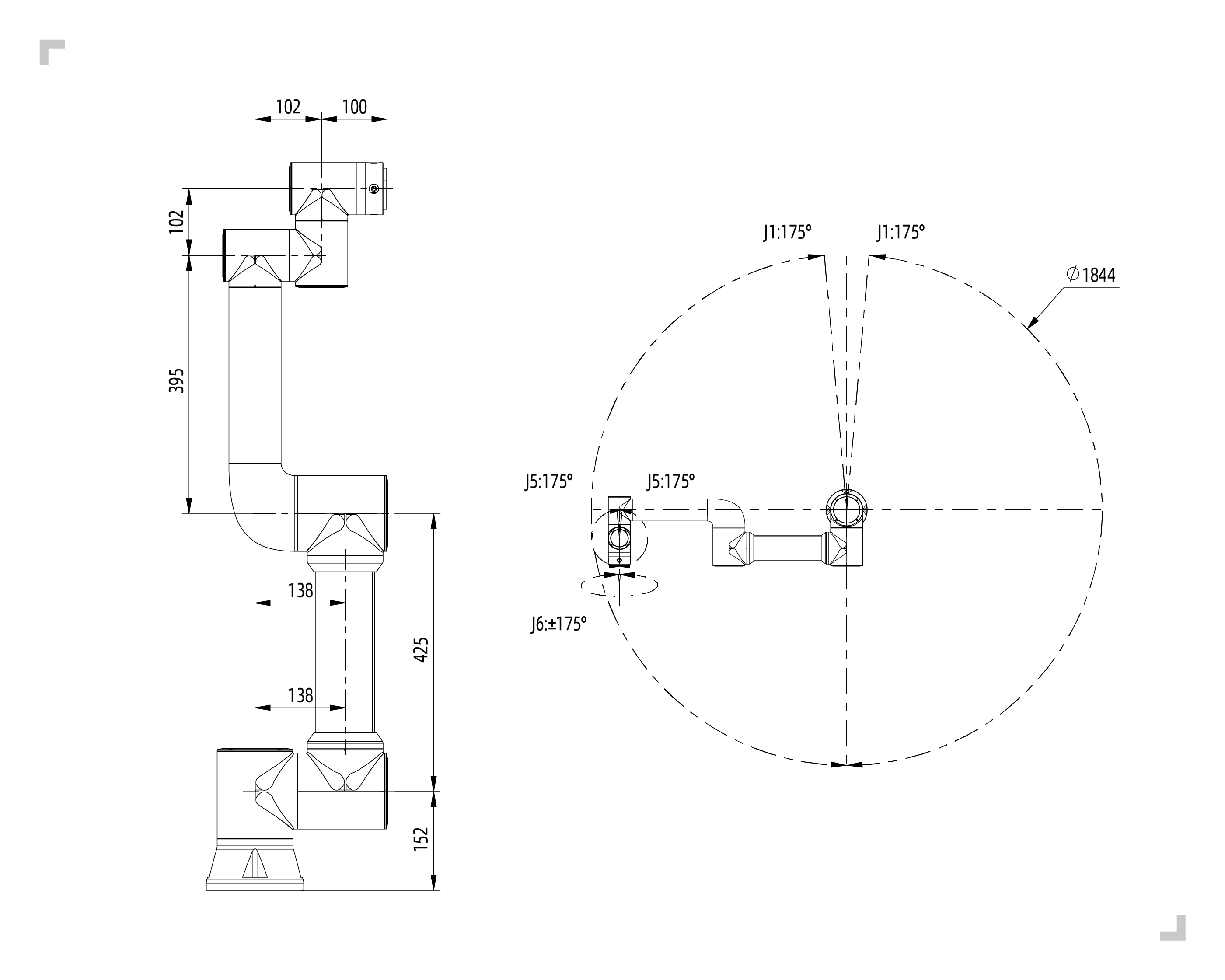
法奥机器人FR5
海康威视MV-CU060-10UC
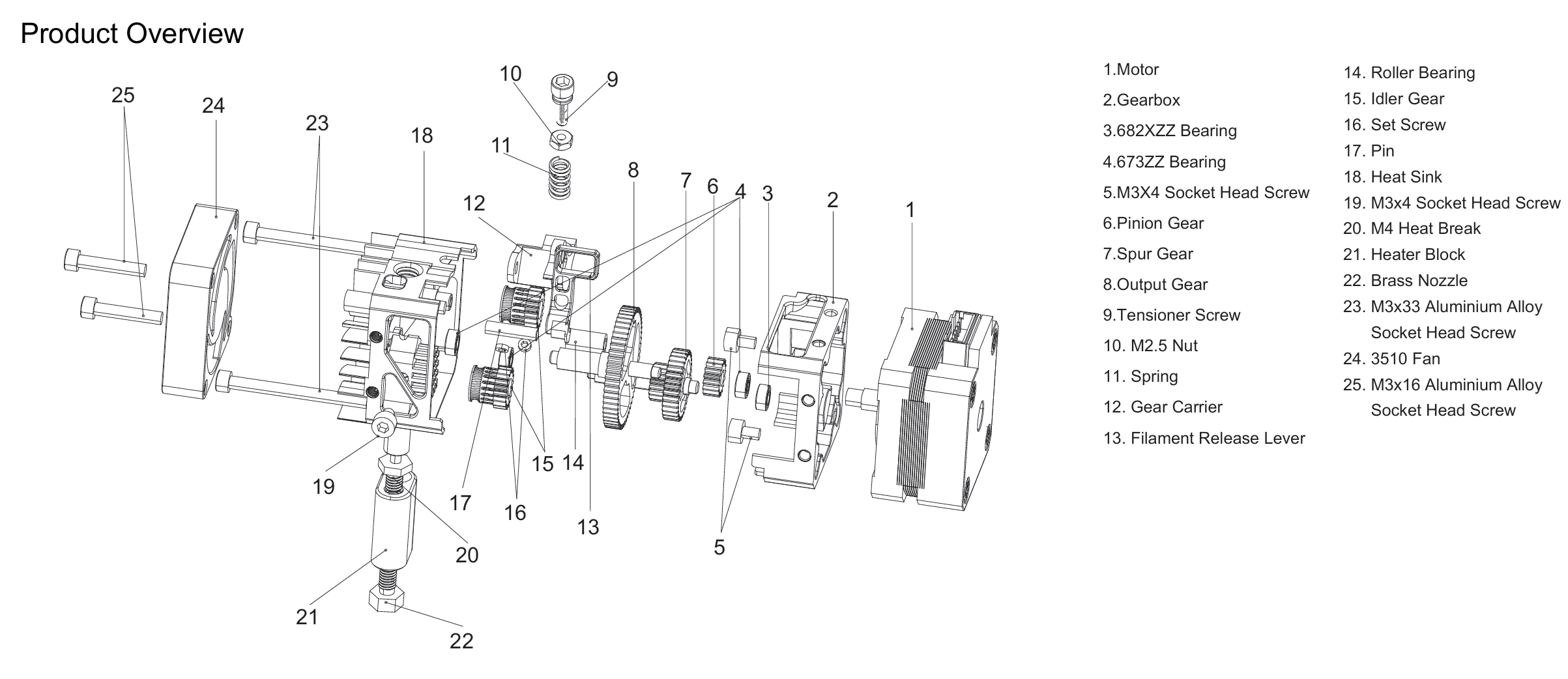
BIQU H2 V2S
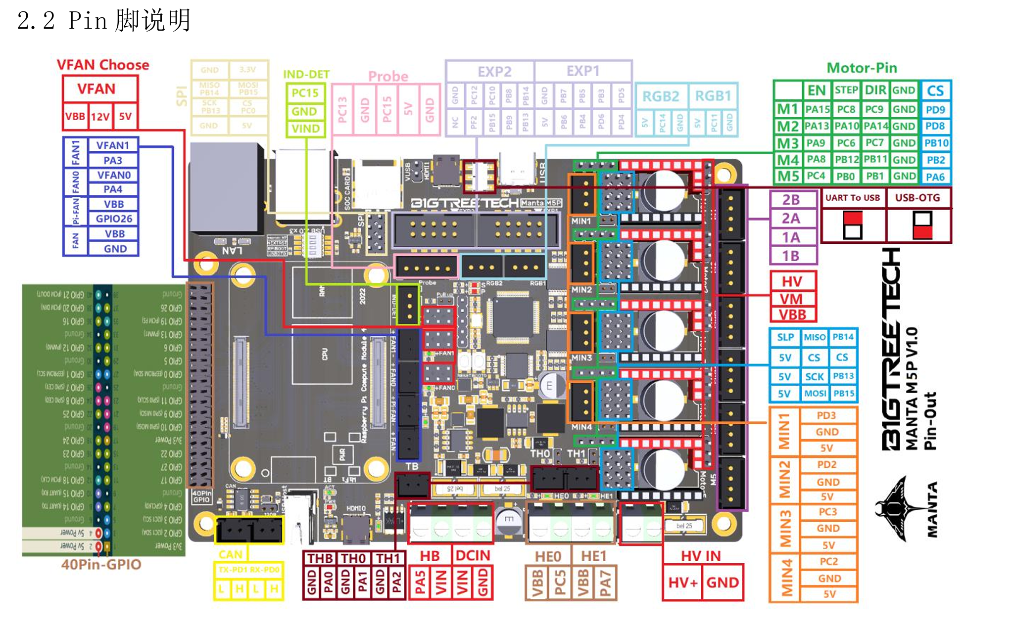
BIQU Manta M5P
我们将笔记本电脑作为核心控制单元,通过不同的通讯协议将各组件串联:
机械臂 :通过以太网(RPC 协议)进行 TCP/IP 通讯。视觉系统 :通过 USB 直连,调用海康官方 SDK。打印头 :PC 通过 HTTP 请求与 Manta M5P 上的 Moonraker API 交互,实现远程 G-code 指令下发。
将PC通过以太网与法奥机器人连接,将PC以太网设置为192.168.58.X网段,此时机器人的IP地址为192.168.58.2
可以通过fairino.Robot.RPC通过RPC与机器人进行通讯
将摄像头通过USB与摄像头连接
可以通过实例化海康威视的MvImport.MvCameraControl_class的类可以与摄像头进行通讯
将H2V2S与Motor1的1A 1B 2A 2B连接,将风扇连接VFAN0和PA4
将加热棒接入HE0继电器,将热敏电阻接入TH0
使用法奥机器人Python SDK
robot/RobotArm.py
1
2
3
4
5
6
7
8
9
10
11
12
13
14
15
16
17
18
19
20
21
22
from robot.fairino import Robotclass RobotArm : def __init__ (self, ip="192.168.58.2" ): try : self.robot_instance = Robot.RPC(ip) ret = self.robot_instance.GetActualToolFlangePose() print ("机器人当前位姿:" , ret) except Exception as e: print ("连接机器人失败:" , e) def get_instance (self ): return self.robot_instance def get_current_pose (self ): return self.robot_instance.GetActualToolFlangePose() def move_to_pose (self, pose, velocity=20 ): ret = self.robot_instance.MoveCart(pose, 0 , 0 , vel=velocity) print ("移动到位姿:" , pose, " 结果:" , ret)
首先在构造函数中实例化fairino的RPC通讯
通过调用GetActualToolFlangePose()获取当前末端法兰位姿
通过调用MoveCart()移动机械臂
调用海康威视的SDK读取摄像头图像image\ImageGrab.py
1
2
3
4
5
6
7
8
9
10
11
12
13
14
15
16
17
18
19
20
21
22
23
24
25
26
27
28
29
30
31
32
33
34
35
36
37
38
39
40
41
42
43
44
45
46
47
48
49
50
51
52
53
54
55
56
57
58
59
60
61
62
63
64
65
66
67
68
69
70
71
72
73
74
75
76
77
78
79
80
81
82
83
84
85
86
87
88
89
90
91
92
93
94
95
96
97
98
99
100
101
102
103
104
105
106
107
108
109
110
111
112
from ctypes import *from MvImport.MvCameraControl_class import *HB_format_list = [ PixelType_Gvsp_HB_Mono8, PixelType_Gvsp_HB_Mono10, PixelType_Gvsp_HB_Mono10_Packed, PixelType_Gvsp_HB_Mono12, PixelType_Gvsp_HB_Mono12_Packed, PixelType_Gvsp_HB_Mono16, PixelType_Gvsp_HB_BayerGR8, PixelType_Gvsp_HB_BayerRG8, PixelType_Gvsp_HB_BayerGB8, PixelType_Gvsp_HB_BayerBG8, PixelType_Gvsp_HB_BayerRBGG8, PixelType_Gvsp_HB_BayerGR10, PixelType_Gvsp_HB_BayerRG10, PixelType_Gvsp_HB_BayerGB10, PixelType_Gvsp_HB_BayerBG10, PixelType_Gvsp_HB_BayerGR12, PixelType_Gvsp_HB_BayerRG12, PixelType_Gvsp_HB_BayerGB12, PixelType_Gvsp_HB_BayerBG12, PixelType_Gvsp_HB_BayerGR10_Packed, PixelType_Gvsp_HB_BayerRG10_Packed, PixelType_Gvsp_HB_BayerGB10_Packed, PixelType_Gvsp_HB_BayerBG10_Packed, PixelType_Gvsp_HB_BayerGR12_Packed, PixelType_Gvsp_HB_BayerRG12_Packed, PixelType_Gvsp_HB_BayerGB12_Packed, PixelType_Gvsp_HB_BayerBG12_Packed, PixelType_Gvsp_HB_YUV422_Packed, PixelType_Gvsp_HB_YUV422_YUYV_Packed, PixelType_Gvsp_HB_RGB8_Packed, PixelType_Gvsp_HB_BGR8_Packed, PixelType_Gvsp_HB_RGBA8_Packed, PixelType_Gvsp_HB_BGRA8_Packed, PixelType_Gvsp_HB_RGB16_Packed, PixelType_Gvsp_HB_BGR16_Packed, PixelType_Gvsp_HB_RGBA16_Packed, PixelType_Gvsp_HB_BGRA16_Packed] def _MV_Save_jpg_image ( frame_info, cam_instance, file_path="tmp.jpg" ): mv_image_type = MV_Image_Jpeg c_file_path = file_path.encode('ascii' ) stSaveParam = MV_SAVE_IMAGE_TO_FILE_PARAM_EX() stSaveParam.enPixelType = frame_info.stFrameInfo.enPixelType stSaveParam.nWidth = frame_info.stFrameInfo.nWidth stSaveParam.nHeight = frame_info.stFrameInfo.nHeight stSaveParam.nDataLen = frame_info.stFrameInfo.nFrameLen stSaveParam.pData = frame_info.pBufAddr stSaveParam.enImageType = mv_image_type stSaveParam.pcImagePath = create_string_buffer(c_file_path) stSaveParam.iMethodValue = 1 stSaveParam.nQuality = 80 mv_ret = cam_instance.MV_CC_SaveImageToFileEx(stSaveParam) return mv_ret def save_img_to_path (path: str ) -> int : try : MvCamera.MV_CC_Initialize() cam = MvCamera() deviceList = MV_CC_DEVICE_INFO_LIST() ret = MvCamera.MV_CC_EnumDevices(MV_USB_DEVICE, deviceList) if ret != 0 : raise Exception("Enum Devices fail! ret[0x%x]" % ret) if deviceList.nDeviceNum == 0 : raise Exception("Find No Devices!" ) stDeviceList = cast(deviceList.pDeviceInfo[int ( 0 )], POINTER(MV_CC_DEVICE_INFO)).contents ret = cam.MV_CC_CreateHandle(stDeviceList) if ret != 0 : raise Exception("Create Handle fail! ret[0x%x]" % ret) ret = cam.MV_CC_OpenDevice(MV_ACCESS_Exclusive, 0 ) if ret != 0 : raise Exception("open device fail! ret[0x%x]" % ret) ret = cam.MV_CC_SetEnumValue("TriggerMode" , MV_TRIGGER_MODE_OFF) if ret != 0 : raise Exception("set TriggerMode fail! ret[0x%x]" % ret) ret = cam.MV_CC_SetFloatValue("Gamma" , 0.25 ) if ret != 0 : print ("Set Gamma failed! ret[0x%x]" % ret) ret = cam.MV_CC_StartGrabbing() if ret != 0 : raise Exception("start grabbing fail! ret[0x%x]" % ret) stOutFrame = MV_FRAME_OUT() memset(byref(stOutFrame), 0 , sizeof(stOutFrame)) ret = cam.MV_CC_GetImageBuffer(stOutFrame, 20000 ) if None != stOutFrame.pBufAddr and 0 == ret: ret = _MV_Save_jpg_image(stOutFrame, cam, path) if ret != 0 : cam.MV_CC_FreeImageBuffer(stOutFrame) raise Exception("save image fail! ret[0x%x]" % ret) cam.MV_CC_FreeImageBuffer(stOutFrame) else : raise Exception("no data[0x%x]" % ret) except Exception as e: print ("Exception occurred: %s" % str (e)) if cam: cam.MV_CC_CloseDevice() cam.MV_CC_DestroyHandle() return -1 finally : MvCamera.MV_CC_Finalize()
save_img_to_path通过调用_MV_Save_jpg_image()内部函数实现把图片保存到指定路径
使用opencv2编写黑色缺陷检测算法image\DefectDetection.py
1
2
3
4
5
6
7
8
9
10
11
12
13
14
15
16
17
18
19
20
21
22
23
24
25
26
27
28
29
30
31
32
33
34
35
36
37
38
39
40
41
42
43
44
45
46
47
48
49
50
51
52
53
54
55
56
57
58
59
60
61
62
63
64
65
66
67
68
69
70
71
72
73
74
75
76
77
78
79
80
81
82
83
84
import cv2import numpy as npdef preprocess_image (image ): """ params: image: 输入的灰度图像(type: numpy.ndarray) output: 预处理后的图像(type: numpy.ndarray) TODO: 去噪声、增强对比度等预处理操作 """ resized_image = cv2.resize(image, (1200 , 800 )) return resized_image def get_defect_edges (image ): """ params: image: 预处理后的图像(type: numpy.ndarray) output: 轨迹点列表(type: list of tuple) [(x, y), ...] """ _, binary = cv2.threshold(image, 100 , 255 , cv2.THRESH_BINARY_INV) contours, _ = cv2.findContours(binary, cv2.RETR_EXTERNAL, cv2.CHAIN_APPROX_SIMPLE) points = [] if contours: max_contour = max (contours, key=cv2.contourArea) epsilon = 0.003 * cv2.arcLength(max_contour, True ) approx_contour = cv2.approxPolyDP(max_contour, epsilon, True ) if cv2.contourArea(approx_contour, oriented=True ) < 0 : approx_contour = approx_contour[::-1 ] for point in approx_contour: x, y = point[0 ] points.append((int (x), int (y))) return points def convert_to_robot_coordinates (points, config=None ): """ params: points: 轨迹点列表(type: list of tuple) [(x, y), ...] config: 坐标转换配置(type: dict) output: 机器人坐标系下的位姿(type: list of tuple) 每个位置包含 (x, y, z, angle_x, angle_y, angle_z) TODO: 将图像坐标转换为机器人坐标系下的位姿 朝向角度固定,z坐标固定高度 """ src_pts = np.float32([[1200 , 0 ], [0 , 0 ], [1200 , 800 ]]) dst_pts = np.float32([[76.40 , -411.46 ], [247.87 , -561.93 ], [179.76 , -300.02 ]]) M = cv2.getAffineTransform(src_pts, dst_pts) if config is None : config = { 'height' : 86 , 'angle_x' : 0.0 , 'angle_y' : 0.0 , 'angle_z' : 0.0 , } positions = [] for x, y in points: robot_x = M[0 , 0 ] * x + M[0 , 1 ] * y + M[0 , 2 ] robot_y = M[1 , 0 ] * x + M[1 , 1 ] * y + M[1 , 2 ] print (f"图像坐标 ({x} , {y} ) -> 机器人坐标 ({robot_x:.2 f} , {robot_y:.2 f} )" ) positions.append((robot_x, robot_y, config['height' ], config['angle_x' ], config['angle_y' ], config['angle_z' ])) return positions
preprocess_image对于输入的灰度图像进行预处理(目前只做了缩放)
get_defect_edges将图片中的黑色部分识别并分割为离散的轨迹点
convert_to_robot_coordinates根据标定的坐标,通过仿射变换,将图像中的坐标转化为实际法兰坐标系中的坐标
挤出头的控制通过 Moonraker API 实现,采用 HTTP POST 请求发送 G-code 指令,并查询打印机状态。代码封装在 Printer 类中,实现了温度控制、挤出控制及风扇管理。
底层通讯逻辑位于 robot/gcode_sender.py,通过 HTTP 协议向 Moonraker 发送控制脚本。
1
2
3
4
5
6
7
8
9
10
11
12
13
14
15
16
17
18
19
20
21
22
23
import requestsdef send_gcode_to_moonraker (gcode_command, api_url="http://localhost:7125" , api_key=None ): """ 通过HTTP POST向Moonraker发送G-code指令 """ headers = {"Content-Type" : "application/json" } if api_key: headers["X-Api-Key" ] = api_key payload = {"script" : gcode_command} try : response = requests.post( f"{api_url} /printer/gcode/script" , json=payload, headers=headers, timeout=10 ) response.raise_for_status() return {"result" : "ok" , "details" : response.json()} except requests.exceptions.RequestException as e: return {"result" : "err" , "details" : str (e)}
该函数封装了对 http://<ip>:7125/printer/gcode/script 接口的调用,允许向运行 Klipper 的 Manta M5P 主板发送标准 G-code 指令。
上层控制逻辑封装于 robot/printer.py,提供了对加热、挤出和状态监控的抽象方法。
1
2
3
4
5
6
7
8
9
10
11
12
13
14
15
16
17
18
19
20
21
22
23
24
25
26
27
28
29
30
31
32
33
34
35
36
37
38
39
40
41
42
43
44
45
46
47
48
49
50
51
52
53
54
55
56
57
58
59
60
61
62
from robot.gcode_sender import send_gcode_to_moonrakerimport requestsimport timeclass Printer : def __init__ (self, api_url="http://localhost:7125" , api_key=None ): self.api_url = api_url self.api_key = api_key def start_heating (self, target_temp=200 ): print (f"[打印头]挤出机开始加热到 {target_temp} °C..." ) gcode = f"M104 S{target_temp} " return self.send_gcode(gcode) def enable_motors (self ): print ("[打印头]启用电机..." ) self.send_gcode("M18 E" ) self.send_gcode("M83" ) return self.send_gcode("G92 E0" ) def start_extrusion (self, feed_rate=600 ): print (f"[打印头]开始挤出,进给速度:{feed_rate} ..." ) return self.send_gcode("START_EXTRUDE" ) def stop_extrusion (self ): print ("[打印头]停止挤出..." ) self.send_gcode("STOP_EXTRUDE" ) return self.send_gcode("G1 E-2 F500" ) def get_extruder_temperature (self ): try : response = requests.get( f"{self.api_url} /printer/objects/query?extruder=temperature" ) data = response.json() return data["result" ]["status" ]["extruder" ]["temperature" ] except Exception: return -1 def waiting_for_temperature (self, target_temp ): while (self.get_extruder_temperature() < target_temp): print (f"当前温度:{self.get_extruder_temperature():.2 f} °C..." ) time.sleep(0.2 ) def start_print (self ): self.stop_fan() self.enable_motors() self.start_heating(200 ) print ("[打印头]等待挤出机加热完成..." ) self.waiting_for_temperature(200 ) print ("[打印头]挤出机加热完成,开始打印..." ) self.start_extrusion() def stop_print (self ): self.stop_extrusion() self.stop_heating() self.start_fan(255 ) self.disable_motors()
温控逻辑:使用 M104 指令设置目标温度,并通过 /printer/objects/query 接口轮询当前 extruder 的温度状态,实现闭环等待 (waiting_for_temperature)。
在开始挤出前,通过 M83 将挤出机设置为相对位置模式,防止累积误差。
start_extrusion 和 stop_extrusion 调用了 Klipper 配置中预设的宏 (START_EXTRUDE/STOP_EXTRUDE) 来控制步进电机持续转动。
在停止挤出时,额外发送 G1 E-2 执行 2mm 的回抽操作,利用物理负压防止熔融耗材滴漏。
流程自动化:start_print 函数实现了标准的 3D 打印准备流程:电机上电 -> 启动加热 -> 阻塞等待温度达标 -> 开启挤出。
联动控制部分由主程序 main.py 实现,该程序作为系统的“大脑”,负责协调视觉模块、机械臂运动模块和打印机控制模块的有序工作。整个工作流程包含系统初始化、视觉处理与路径规划、以及打印执行三个主要阶段。
程序启动后,首先加载配置文件 mapping.json 获取 Klipper API 的地址,并分别实例化打印机控制对象 Printer 和机械臂控制对象 RobotArm。
为了确保运行安全,程序定义了信号处理函数 signal_handler,在接收到终止信号时能够紧急停止打印任务。建立连接后,机械臂会首先移动到一个安全的复位姿态,准备进行后续操作。
1 2 3 4 5 6 7 8 9 printer_e = printer.Printer(api_url=api_url, api_key=None ) try : robot_arm = RobotArm.RobotArm(ip="192.168.58.2" ) except Exception as e: exit(1 ) robot_arm.move_to_pose([142.59 , -283.73 , 567.82 , -87.18 , -0.07 , -133.48 ], velocity=30 )
在机械臂到达观测位置后,系统调用 ImageGrab 截取当前工作台的图像,并保存为 original.jpg。随后,利用 DefectDetection 模块对图像进行灰度化和预处理,识别出待修复(或打印)区域的边缘轮廓点。
识别到的图像坐标点(像素坐标)通过 convert_to_robot_coordinates 函数结合标定参数,被批量转换为机械臂基坐标系下的空间坐标(x, y, z, rx, ry, rz),形成最终的打印轨迹点集 desc_positions。
1 2 3 4 5 6 7 gray_img = cv2.cvtColor(cv2.imread("original.jpg" ), cv2.COLOR_BGR2GRAY) proced_img = DefectDetection.preprocess_image(gray_img) points = DefectDetection.get_defect_edges(proced_img) desc_positions = DefectDetection.convert_to_robot_coordinates(points, mapping_config)
这是系统的核心环节,实现了机械臂运动与挤出机挤出的同步配合。逻辑如下:
就位 :机械臂以较快速度(velocity=20)移动到轨迹的第一个点(起始点)。启动挤出 :调用 printer_e.start_print(),此时打印头开始加热并启动挤出电机。轨迹跟随 :程序遍历剩余的轨迹点,控制机械臂以恒定的低速(velocity=3)沿计算出的路径移动。由于挤出机已开启,机械臂的移动轨迹即形成了实体的 3D 打印线条。任务结束 :当所有点位执行完毕后,打印结束。
1 2 3 4 5 6 7 8 9 10 11 12 13 14 robot_arm.move_to_pose(desc_positions[0 ], velocity=20 ) desc_positions.pop(0 ) printer_e.start_print() index = 0 for position in desc_positions: print ("[%d/%d]点位" % (index + 1 , len (desc_positions)), position) robot_arm.move_to_pose(position, velocity=3 ) index += 1
通过这种方式,系统成功实现了“眼”(视觉定位)、“手”(机械臂运动)与“笔”(3D 打印头)的协同工作,完成了在非平面或特定路径上的自动化增材制造任务。
本项目成功构建了基于法奥 FR5 工业机械臂与 BIQU H2 V2S 挤出头的自动化 3D 打印系统,实现了从视觉感知到自动化执行的完整闭环。系统通过集成海康威视工业相机获取环境图像,利用 OpenCV 算法提取黑色缺陷边缘并将其从图像坐标系映射至机器人基坐标系,随后驱动机械臂带动挤出头沿规划轨迹运动。在控制层面,通过封装 Moonraker API 实现了对打印头加热、挤出及风扇状态的远程精确调控,并依托主控程序的流程编排,确保了机械臂末端位姿与挤出流量在时空维度上的高效协同。
该项目的实际意义我觉得在于把整个系统构建出来并成功跑通了,虽然在工程方面仍然很简陋,但是基本的框架已经确定,通过不同的视觉算法与轨迹控制的组合,我们可以有很大的想象空间,例如:
动态流率补偿:目前挤出速度恒定,未来可根据机械臂末端的实际加速度动态调整挤出机转速(Pressure Advance)。
多自由度优势:目前仅使用了三自由度运动,未来可探索 45° 倾斜打印或在非平面基底上进行曲面增材制造。
工业机械臂与 3D 打印的结合,我觉得仍然拥有很大前景